
Introduction
Hello all, As I progress on my 99 F150 build I realized that it would be nice to replace the original oil pressure switch used by Ford with an actual gauge. So, I have decided to implement this via a simple ATTINY88 Micro Development Board. Like this one from Amazon. Below, I will discuss the plan to accomplish this feature and still maintain the original check oil light. Oh, the benefit to this is that I will have the ability to program exactly when the check oil light turns on. Or, to why the check oil light would turn on. Such as, some other failure condition in the future such as if I add oil temp to the mix next.

The Plan
This is not to complex of a plan. For example, it is using the Development Board so I do not have to mount the ATTiny88 on an pcb board it is already done. It also provides a breakout of the micro’s I/O so now all I have to do is take the 12v (actually more like < 16v) and convert it to a constant 5v. No problem, just use a standalone regulator supply like this. Then, I have to send out the signal to the original circuit so the dash check oil light works as it did; well at least, similarly to original as I want it to work. Here, I referenced the Mitchell Manuals for the circuit that controls the oil light. Below, is from the Instrument Cluster wire schematic.

Great, this is not to complex! All I have to due is ground out that wire so a simple Mosfet negative switch will work wonderful and I can easily control this with the ATTiny88 I/O. So, the 2N7000 Mosfet will work here just fine without any further Mosfet driver. It has a VGS(th) of 2.5v so should switch on fine to drive circuit to ground. Especially true since it is only driving a wire that connects to another Microcontroller so there is not a high current flow in this circuit. Probably < 1mA of current flows in this circuit. The 2N7000 can handle 500 mA current all day long.
Below is an example of the switch circuit; and my circuit will replicate this design R gen is going to be a 1K Ohm resistor just to handle the gate capacitance and not overdrive the ATTiny88 IO ports current.

After looking at the ATTiny88 it is a 5v capable device so no voltage leveling needs to be done. Here is an example circuit if you wanted to do 3.3v max voltage leveling.

Also, V1 is grounded; and, V2 is max of 5v. VP should be set to 3.3 volts to prevent the possibility of going over 3.3 volts. U?A could be a LM358 for example as it is a great single supply op-amp. However, since I am using ATTiny then analog input can go to 5v.
The Pressure Transceiver
Now, the oil pressure transceiver is this one 100 psi capable one. The nice thing about this one is that it is quite linear across the supported pressure range. That is, Output: 0.5-4.5V linear voltage output. 0 psi outputs 0.5V, 50 psi outputs 2.5V, 100 psi outputs 4.5V. So a simple voltage scale work well to calculate output of ADC on ATTiny Arduino has a MAP function but it only works on int so here is the one for float types.
long map(long x, long in_min, long in_max, long out_min, long out_max)
{
	return (x - in_min) * (out_max - out_min) / (in_max - in_min) + out_min;
}
LCD Display
Finally, the last piece of this puzzle is the LCD display. I have chosen this display from Amazon. With that I will be able to compile in a nice readable display that is fully eliminated. I have also chosen to code this all in PlatformIO via Visual Studio Code (VSC). So, I have added the PlatformIO extension to VSC. Then, I added the following libraries
- Tiny4kOLED – For the display
- sstaub/Ticker – for non-blocking thread like action.
The Execution
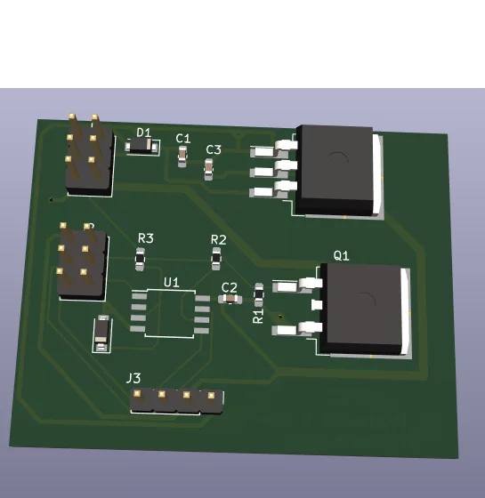
BOM
| Comment | Designator | Footprint | LCSC |
| 10uF | C1,C3 | Capacitor_SMD:C_0603_1608Metric_Pad1.08×0.95mm_HandSolder | C194427 |
| .1uF | C2 | Capacitor_SMD:C_0603_1608Metric_Pad1.08×0.95mm_HandSolder | C2180759 |
| 1 amp | D1 | Diode_SMD:D_SOD-123F | C126484 |
| 5.1 v | D2 | Diode_SMD:D_SOD-123 | C151576 |
| I/O Connector | J1 | Connector_PinHeader_2.54mm:PinHeader_2x03_P2.54mm_Vertical | C3348967 |
| ISP Prog | J2 | Connector_PinHeader_2.54mm:PinHeader_2x03_P2.54mm_Vertical | C3348967 |
| LCD Conn | J3 | Connector_PinHeader_2.54mm:PinHeader_1x04_P2.54mm_Vertical | C3338160 |
| PHB21N06LT,118 | Q1 | Package_TO_SOT_SMD:TO-263-2 | C552623 |
| 10M | R1 | Resistor_SMD:R_0603_1608Metric_Pad0.98×0.95mm_HandSolder | C2653999 |
| 1k | R2,R3 | Resistor_SMD:R_0603_1608Metric_Pad0.98×0.95mm_HandSolder | C1870265 |
| ATtiny85-20S | U1 | Package_SO:SOIC-8W_5.3×5.3mm_P1.27mm | C615549 |
| LM1085-5.0 | U2 | Package_TO_SOT_SMD:TO-263-3_TabPin2 | C434505 |

I have also added this to github here.
The top of the PCB

